Reliable assembly depends on more than tightening a screw and hoping the joint holds. Compression Screws provide controlled clamping force for components that must remain secure under vibration, movement, or repeated servicing. Their design can help distribute pressure across mating surfaces, reducing localized damage and improving assembly consistency.
In practical work, engineers select these fasteners according to material strength, joint geometry, load direction, and operating temperature. A screw used in thin aluminum behaves differently from one installed in steel or reinforced polymer. Thread engagement, washer selection, torque settings, and surface condition all influence performance. Small details matter.
They matter greatly.
Experienced technicians often inspect the joint before installation. They check for misalignment, burrs, damaged threads, and uneven contact faces. Torque tools should be calibrated, while installation records can support quality control and future maintenance. Testing may include vibration exposure, repeated tightening, pull-out evaluation, or dimensional checks, depending on the application.
However, Compression Screws are not a universal solution. No fastener solves everything. Excessive torque can deform delicate parts, while insufficient torque may allow movement. Design assumptions can also fail when temperature changes or materials expand at different rates. A reliable choice requires documented specifications, suitable materials, and verification under realistic conditions.
This guide examines why Compression Screws remain valuable in demanding assemblies. It considers their mechanical advantages, installation practices, material compatibility, and limitations. The goal is practical guidance, not exaggerated certainty. Good fastening decisions come from evidence, careful inspection, and a willingness to question the first design that appears adequate.
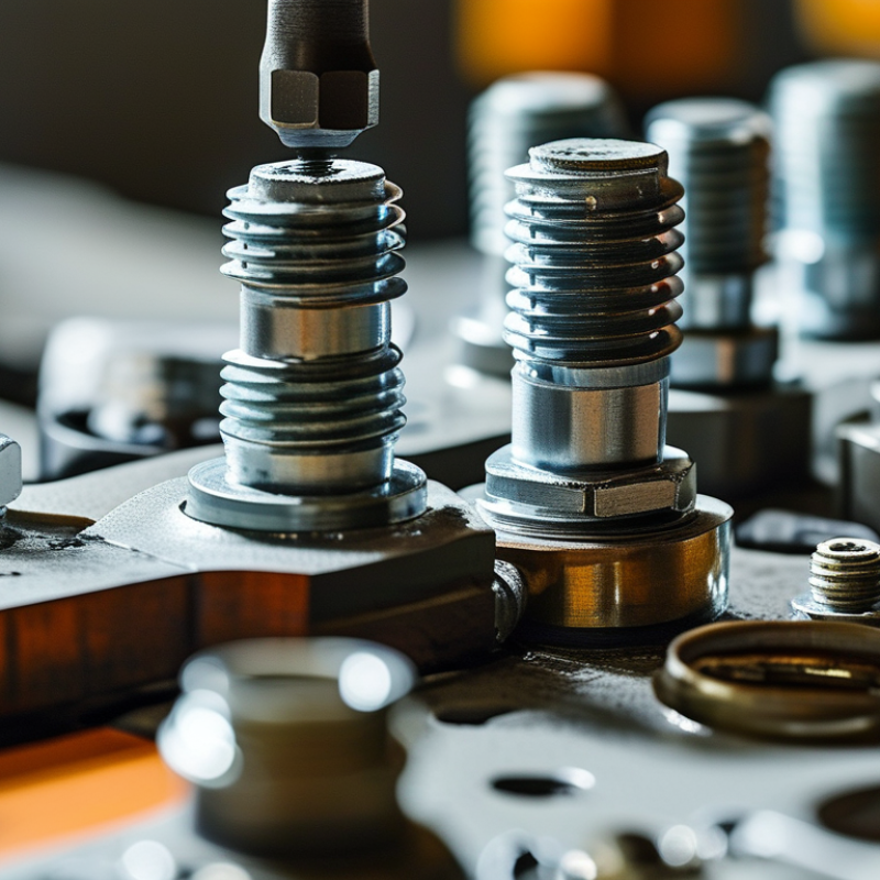
Compression screws are fasteners designed to apply controlled pressure between joined parts. Unlike a standard screw, many include a shoulder, spacer, or captive washer. This feature limits travel and protects the assembly from excessive crushing.
When tightened, the threaded section pulls the screw head toward the mating surface. The shoulder then compresses a panel, gasket, spring, or soft insert. The result is stable clamping without relying entirely on the operator’s judgment. It is simple. Friction decides much of the outcome. A widely cited aerospace fastener design manual notes that only about 10–20% of applied tightening torque usually becomes useful preload; the rest is lost through friction. Surface finish, lubrication, and thread condition therefore matter greatly.
This explains why compression screws suit enclosures, electrical panels, vibration-prone equipment, and thin composite structures. The 2024 Global Industrial Fasteners Market report estimated worldwide demand at more than USD 90 billion, reflecting the scale of modern fastening applications. However, market size does not prove joint reliability. Engineers should verify compression distance, material strength, and repeated-load performance through torque testing and inspection. I would not treat torque alone as proof of correct assembly. A damaged gasket may look secure while losing pressure later. Field experience also shows that overtightening remains a common mistake, especially when soft materials are involved. A calibrated driver and a defined compression limit are safer than guesswork.
| Data Dimension | Compression Screw | How It Works in an Assembly | Practical Benefit |
|---|---|---|---|
| Basic definition | A threaded fastener designed to apply controlled clamping force while limiting or guiding the compression of a component. | The screw advances into a threaded hole or nut, while its shoulder, sleeve, spacer, or controlled-length shank manages the final clamping position. | More predictable assembly than a simple screw used without a compression-control feature. |
| Primary load | Axial preload, also called clamping force. | Torque or another tightening method creates tension in the screw and compression between the assembled parts. | Maintains contact between mating components during service. |
| Compression control | Controlled by a shoulder, fixed spacer, sleeve, or precisely defined screw length. | When the controlling feature reaches its mating surface, additional tightening is restricted or transferred through the intended load path. | Reduces the risk of crushing seals, plastics, thin sheet, circuit boards, or other sensitive parts. |
| Typical applications | Enclosures, covers, panels, electronics, sensors, brackets, soft-material interfaces, and assemblies requiring repeatable spacing. | The fastener joins the parts while maintaining a defined stand-off distance or limiting surface compression. | Supports consistent fit, alignment, and serviceability. |
| Common screw materials | Carbon steel, alloy steel, stainless steel, and other materials selected for strength, corrosion resistance, temperature, and compatibility requirements. | Material properties determine tensile capacity, wear resistance, corrosion behavior, and compatibility with the mating components. | Allows the fastener to be matched to the mechanical and environmental conditions. |
| Thread engagement | Must be sufficient for the screw diameter, material strength, applied preload, and joint design; no single engagement length suits every assembly. | Engaged threads transfer the screw load into the nut or tapped hole. Insufficient engagement can cause stripping or pull-out. | Improves joint strength and reduces thread damage when correctly designed. |
| Load distribution | Can use a larger shoulder, washer, or spacer to spread the contact load over a wider area. | The larger contact area lowers local surface pressure compared with a small screw head acting directly on a soft material. | Helps minimize indentation, deformation, and localized damage. |
| Installation method | Typically installed with a calibrated torque tool, although angle control, tension control, or other methods may be specified. | The selected installation method controls screw preload and helps achieve repeatable joint performance. | Improves process consistency in manual and automated assembly. |
| Torque reference | Torque is application-specific and depends on diameter, thread pitch, material grade, lubrication, coating, friction, and required preload. | A torque value should be validated through engineering calculations or testing rather than copied from a general table. | Avoids under-tightening, over-tightening, thread stripping, and fastener failure. |
| Vibration behavior | Provides a defined joint geometry, but may still require a suitable locking feature where vibration or cyclic loading is present. | The joint remains reliable when preload, thread engagement, friction, and locking provisions are correctly designed. | Supports resistance to loosening without relying on compression control alone. |
| Dimensional control | May include a fixed shoulder length, sleeve length, or stand-off dimension selected for the joint stack-up. | The controlled dimension limits variation caused by operator tightening or small differences in component thickness. | Improves repeatability of gaps, clearances, and component positioning. |
| Failure risks to evaluate | Thread stripping, screw yielding, fatigue, galling, corrosion, excessive compression, insufficient preload, and loosening. | Performance depends on joint stiffness, load direction, temperature, vibration, tolerances, surface condition, and installation control. | Encourages validation through calculation, prototype testing, and production inspection. |
| Why choose one? | A suitable compression screw combines fastening, spacing, and compression limiting in one engineered assembly element. | It creates clamping force while helping preserve the geometry and condition of the components being joined. | Reliable assembly, repeatable quality, reduced component damage, and easier maintenance. |
| Engineering note: Actual screw size, material, thread engagement, preload, torque, shoulder geometry, and locking method must be selected and validated for the specific joint, materials, loads, and operating environment. | |||
Compression screws support reliable assembly by combining controlled clamping force with simple installation. Their threaded bodies pull mating parts together, while the head distributes pressure across the contact surface. This reduces shifting during handling and routine vibration. Material strength matters, but it is only one part of the design. Thread pitch, screw diameter, head shape, and engagement length must match the joint. A strong screw can still fail when the surrounding material is weak.
Tips: Check the required clamp load before choosing a size. Use a torque-controlled tool during installation. Inspect threads for damage, contamination, or poor alignment. Allow enough engagement without creating unnecessary stress. For outdoor or humid environments, verify corrosion resistance and finish compatibility. Small details often decide whether an assembly stays stable.
In practical assembly work, compression screws are valuable because they allow repeatable fastening and easier servicing. A captive or accessible head can reduce lost hardware during maintenance. Proper tolerances also prevent loose movement between panels, brackets, or covers. However, the first design choice is not always correct. Excessive torque may deform thin materials, while insufficient torque can cause gradual loosening. Testing under heat, vibration, and repeated service conditions provides stronger evidence than appearance alone. Record installation torque and inspection results. That information supports consistent quality and exposes weak assumptions before production expands.
Compression screws improve joint stability by creating controlled clamping force between connected parts. This force keeps surfaces seated during vibration, movement, and repeated loading. When the screw is tightened correctly, it can also guide components into closer alignment. Small gaps become less likely to grow during service.
In practical assembly work, alignment starts before tightening. Clean contact surfaces matter. So do accurate pilot holes. A compression screw cannot correct severely mismatched parts. It may only hide the problem for a while. I have seen joints shift because installers focused on torque but ignored uneven surfaces. That mistake is easy to repeat. The correct screw length, thread engagement, and washer choice also affect pressure distribution. Uneven pressure can distort thin panels or damage softer materials.
Tips: Use a calibrated torque tool and follow the engineering specification. Tighten gradually, using a cross-pattern when several screws share one joint. Check the joint after initial loading. Look for movement, visible gaps, or damaged threads. Do not guess. Record torque values and inspect alignment with a straightedge or measuring gauge. Material differences deserve attention too. Steel screws joining aluminum parts may require suitable isolation and corrosion controls. In some applications, a compression screw needs a locking feature or periodic inspection. That depends on vibration, temperature, and maintenance access. Testing under realistic loads is wiser than relying on appearance alone.
Choosing a compression screw begins with the joint, not the catalog. Measure the required clamp load, compression travel, thread engagement, and available installation space. A screw that looks strong may still damage a soft gasket or distort a thin panel. Small details matter.
Grand View Research estimates that the global fasteners market will reach about USD 116 billion by 2030. This growth reflects rising demand for controlled, repeatable assembly across industrial equipment. Yet market growth does not make selection easier. For each application, match the screw’s material to corrosion exposure, temperature, and contact surfaces. Stainless steel suits humid areas, while hardened alloys may better resist repeated loading. Check the load rating at the actual operating temperature, not only at room temperature.
Torque alone can mislead. Friction, lubrication, and surface finish can change achieved preload significantly. NASA’s Fastener Design Manual stresses joint preload, embedment, and separation resistance during fastener design. Use a calibrated torque tool, then verify compression with a test fixture when failure would be costly. I have seen assemblies pass initial inspection and loosen after thermal cycling. That result deserves more investigation, not a larger screw. Select a compression screw with suitable travel, a stable head design, and clear adjustment control. Leave enough thread engagement. Avoid guesswork.
Why Choose Compression Screws for Reliable Assembly?
Installation Factors That Affect Compression Screw Performance
Compression screws provide controlled clamping when parts need secure fastening without excessive distortion. Their performance depends heavily on installation conditions. In field assembly, I have seen small setup errors create uneven pressure, loose joints, and damaged surfaces.
Match the screw length to the material stack. Too little thread engagement can reduce holding strength. Too much length may interfere with internal components. The hole diameter also matters. A tight hole can prevent proper compression, while a loose hole may allow movement. Keep the parts aligned.
Alignment is critical.
Use a calibrated torque tool when the specification allows it. Excessive torque can crush softer materials, especially plastics, thin panels, and composite sheets. Insufficient torque may leave gaps that invite vibration or moisture. A washer can distribute pressure across delicate surfaces, but it cannot correct poor alignment.
Clean contact surfaces before installation. Oil, dust, and burrs can change friction and produce misleading torque readings. Check the screw head, threads, and mating surface for damage. In humid or corrosive environments, material compatibility deserves careful review. I once treated torque as the main control point, but surface condition caused the larger variation. That experience changed my inspection routine.
Compression may also relax over time. Thermal cycling, vibration, and material creep can reduce clamp load. For critical assemblies, inspect sample joints after testing rather than trusting installation records alone. A reliable process needs both accurate installation and honest follow-up.
Installation Factors That Affect Compression Screw Performance
This chart shows the estimated preload generated by an M6 screw as tightening torque increases. Values are calculated using the engineering relationship T = K × F × d, assuming a 0.006 m nominal diameter and typical friction factors of K = 0.20 for dry threads and K = 0.15 for lubricated threads. Actual results vary with thread condition, material, washer design, alignment, and torque-tool accuracy.
It is a fastener that applies controlled pressure between joined parts. It may include a shoulder, spacer, or captive washer. These features limit travel. They help prevent crushing.
Tightening pulls the screw head toward the mating surface. The shoulder then compresses a gasket, panel, spring, or soft insert. Friction affects the final preload. Torque is not the whole story.
They suit enclosures, electrical panels, vibration-prone equipment, and thin composite structures. They are useful when stable clamping matters. They can protect delicate surfaces.
Start with the joint, not the catalog. Measure clamp load, compression travel, thread engagement, and installation space. Check temperature and corrosion exposure. A strong-looking screw may still damage a soft gasket.
No. Torque can be changed by friction, lubrication, surface finish, and damaged threads. Use a calibrated tool when suitable. Verify compression with a test fixture for critical joints. Torque alone can mislead.
Incorrect length, poor alignment, and unsuitable hole diameter can weaken the joint. Too little engagement reduces holding strength. Too much length may contact internal parts. Keep the parts aligned.
Clean oil, dust, and burrs from contact surfaces. Use a washer when pressure needs wider distribution. Avoid excessive torque on plastics, thin panels, and composite sheets. Guesswork is risky.
Yes. Thermal cycling, vibration, and material creep may reduce clamp load. A joint can look secure at first. Later, gaps or loosening may appear. Inspect sample joints after testing.
Compression Screws are designed to create controlled clamping force between assembled components, helping maintain a secure connection without relying on complex hardware. Their working principle combines threaded engagement with a compressive load that draws parts together, supports consistent contact, and helps reduce movement during operation. Key design features, such as thread form, head style, material selection, and dimensional accuracy, contribute to reliable assembly and long-term performance.
By improving joint stability and alignment, Compression Screws can help prevent shifting, gaps, and uneven loading in a wide range of applications. Selecting the correct screw requires consideration of component materials, load requirements, available space, and environmental conditions. Proper installation is equally important: suitable torque, accurate hole preparation, clean contact surfaces, and appropriate tightening procedures help achieve the intended compression without damaging the joint. When design and installation factors are carefully managed, compression screws provide a practical and dependable solution for repeatable assembly.

Synoviq Medical